
As a programmer, I consider myself to be a writer of a particular kind, and with many writers I share a passion for old typewriters. The idea of being able to write code on a typewriter’s keyboard has been intriguing me for quite some time, especially after a bit of experimenting with mechanical keyboards.
When I started this project, I had only a vague idea of the final result; I just wanted to build a laptop computer on top of an old typewriter. Later on the project, its key concepts became clear to my mind:
- To be really portable, the machine should be totally wireless
- Hence be battery powered
- For the display I will use a tablet running a VNC client to show the remote desktop of the embedded PC
- After the electronic conversion, the machine should still work fine as a standard typewriter
- Maintain the original sound and feel of the keyboard during the electronic operational mode
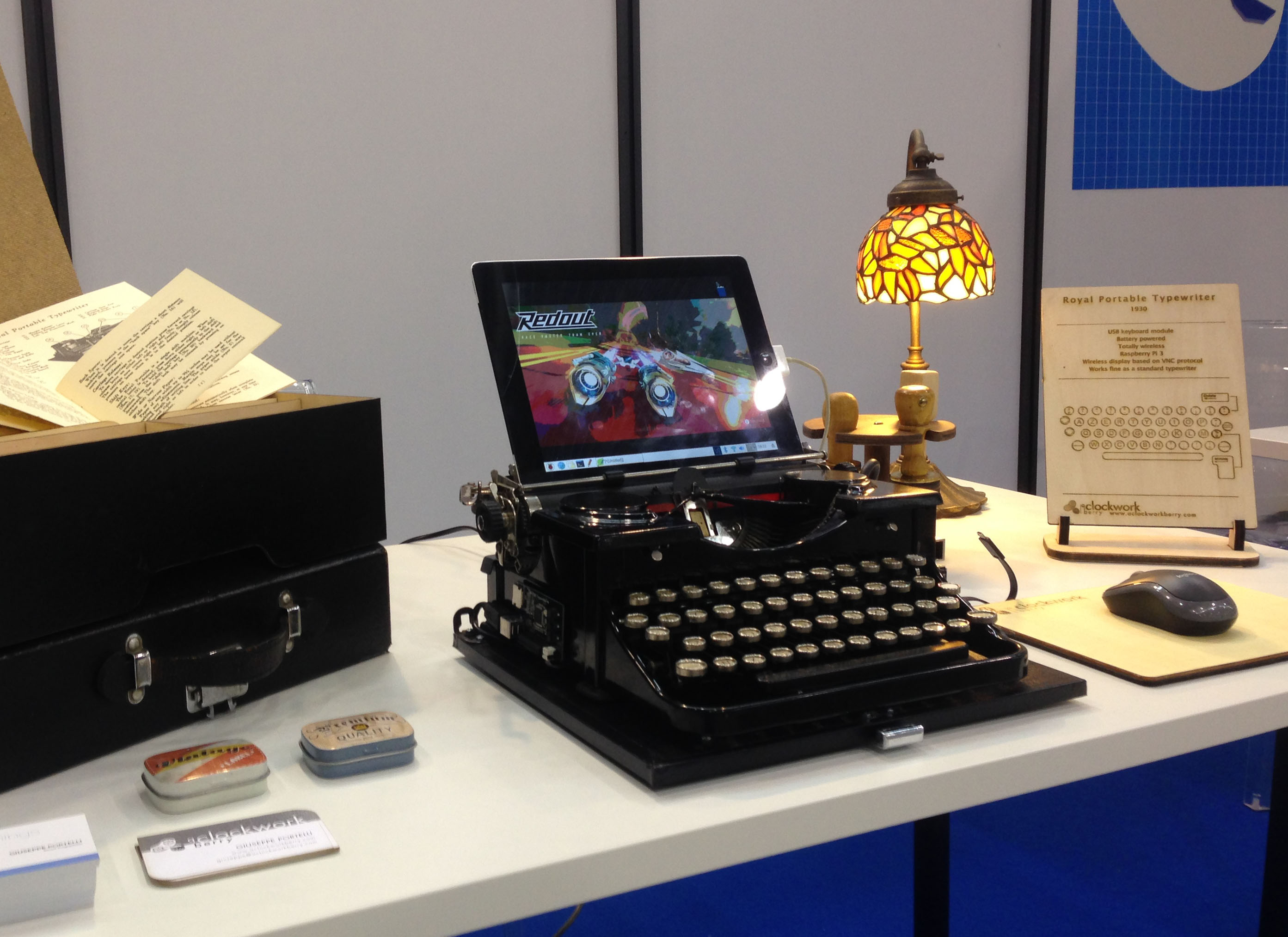
The typewriter at the 2017 Maker Faire in Rome
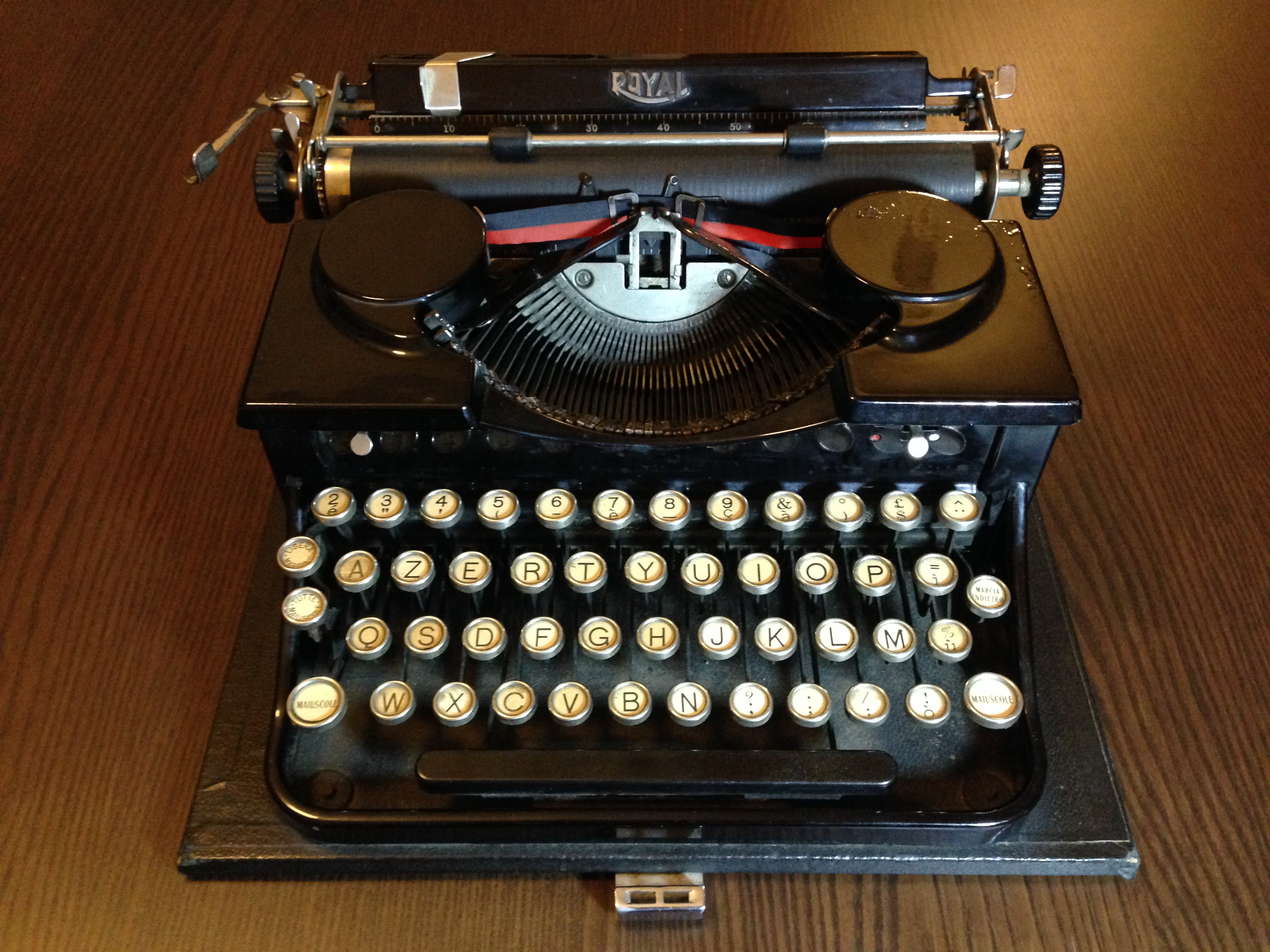
The Royal Portable Typewriter
Before starting the project, I had to find a typewriter. I had a couple of models in mind, a Remington Portable type 3 and a Royal Portable. At the end my choice fell on the Royal and I was lucky enough to find one in my town in pretty good conditions. A black Royal Portable from 1930 with an italian layout keyboard complete with its wooden case. Overall the typewriter was in very good shape: the keyboards where all working and even the case handle made in leather (rare for a machine of almost 90 years) was on its place. The only problems were some scratches on the right ribbon spool cover and the color lever which cannot be set in the stencil position.


Restoring the typewriter
The first thing I did on the machine was cleaning up all the dust collected inside its mechanisms during the last 90 years. You should avoid using cotton buds soaked in alcohol, cause it contains water which could make your machine rust. But I didn’t avoid water, indeed, since I soaked the machine in water with dishwashing liquid. Then I rapidly dried it with an hair dryer. I also removed the old ink encrusted on the hammer keys which was closing the holes in letters like a, e, p, 8.
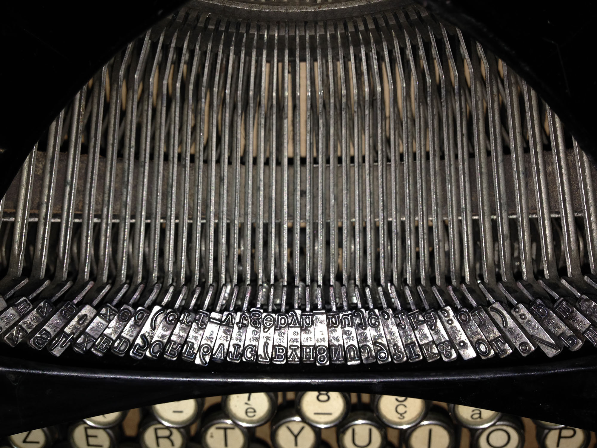
The hammers just cleaned up

The typewriter disassembled
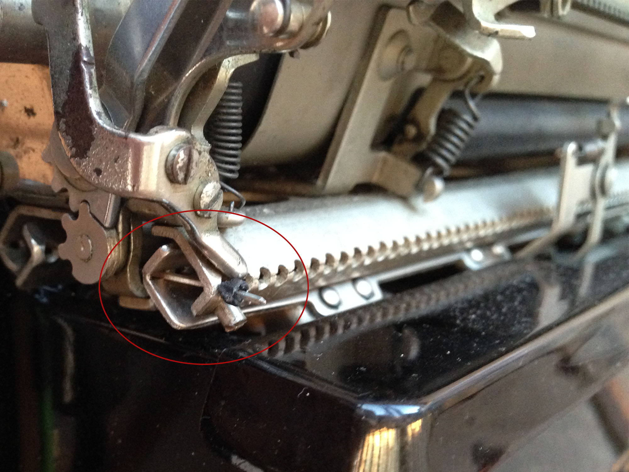
The next step, with the machine disassembled, was fixing the color lever which could not be set into stencil position. The problem turned out to be a cylindrical clamp used to transmit the linear movement of the lever into a rotational one on a shaft. A screw on that clamp was touching the body of the machine thus preventing the complete rotation of the mechanism. Moving the clamp some millimeters to the left fixed the problem.
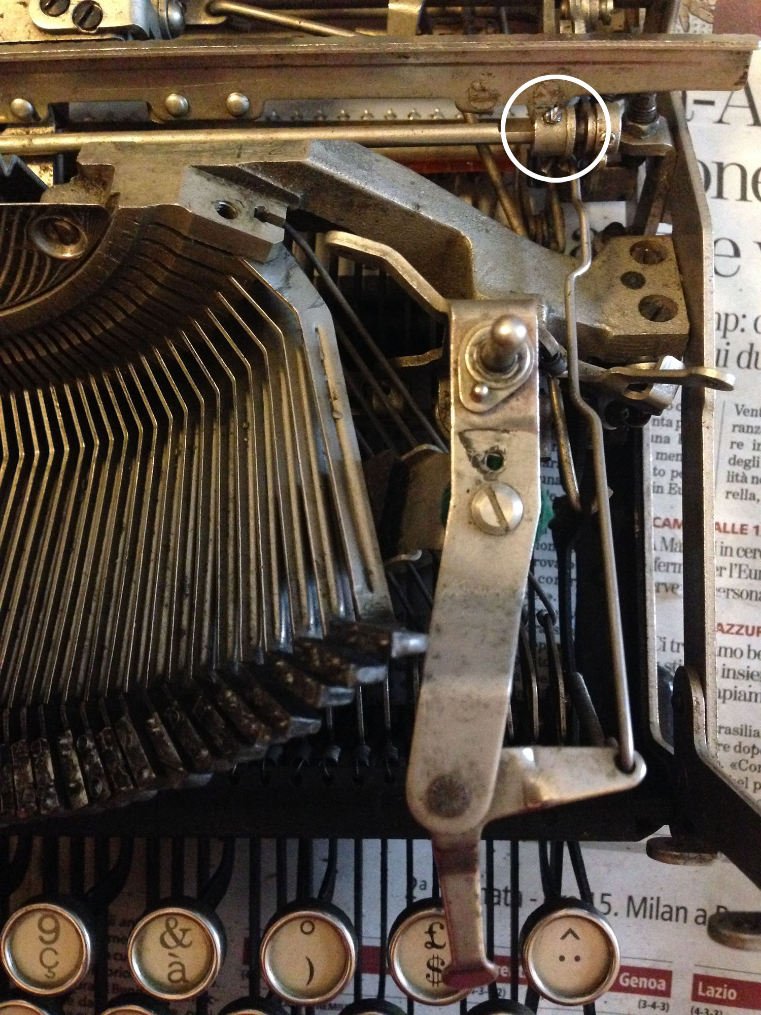
In the white circle, the clamp with the screw blocking the rotation of the shaft
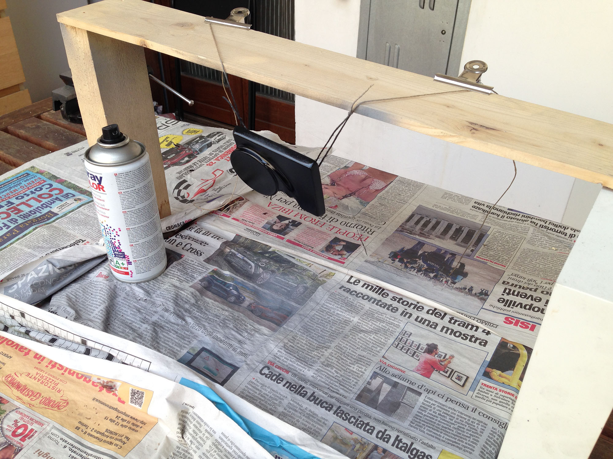
In the last step of the typewriter restoration I repainted the ribbon spool cover with the scratched surface. First I sanded it to remove the old paint, then I applied two coats of primer and two coats of black.
A technique I use to avoid dust when working with spray paint is cleaning up the air with a water sprayer. The little floating drops of water created by the sprayer collect all the dust in the air. Make sure to spray the water in the air just before start painting (if you see a rainbow you are doing it well), wait for the water to fall down, then you can put in place your object and start painting. Avoid putting too much paint with each coat to allow for fast drying and preventing the creation of drops on the surface.


Reassembling the typewriter carriage
One of the most difficult part to reassemble, after completing the restoration, was the carriage. The problem with this part is the difficulty to install by hand the small elements – washers and bearing balls – which allow the carriage to move smoothly on the rail. This difficulty is increased by the fact that, during the installation, a string connected to a spiral spring is constantly pushing the carriage outside its rail.
After hours spent trying different techniques (I used magnets at some point), I finally found a good way to install the carriage with a bit of help from gravity.
As you can see in the animation below, I’m placing the bearing balls with their gear washers one at a time on the rails with the machine positioned vertically. In this way the ball’s weight will keep it in place on the rail while I concentrate on carefully pushing the carriage rail in. After inserting the third ball, I turn the machine upside down to insert the last one.

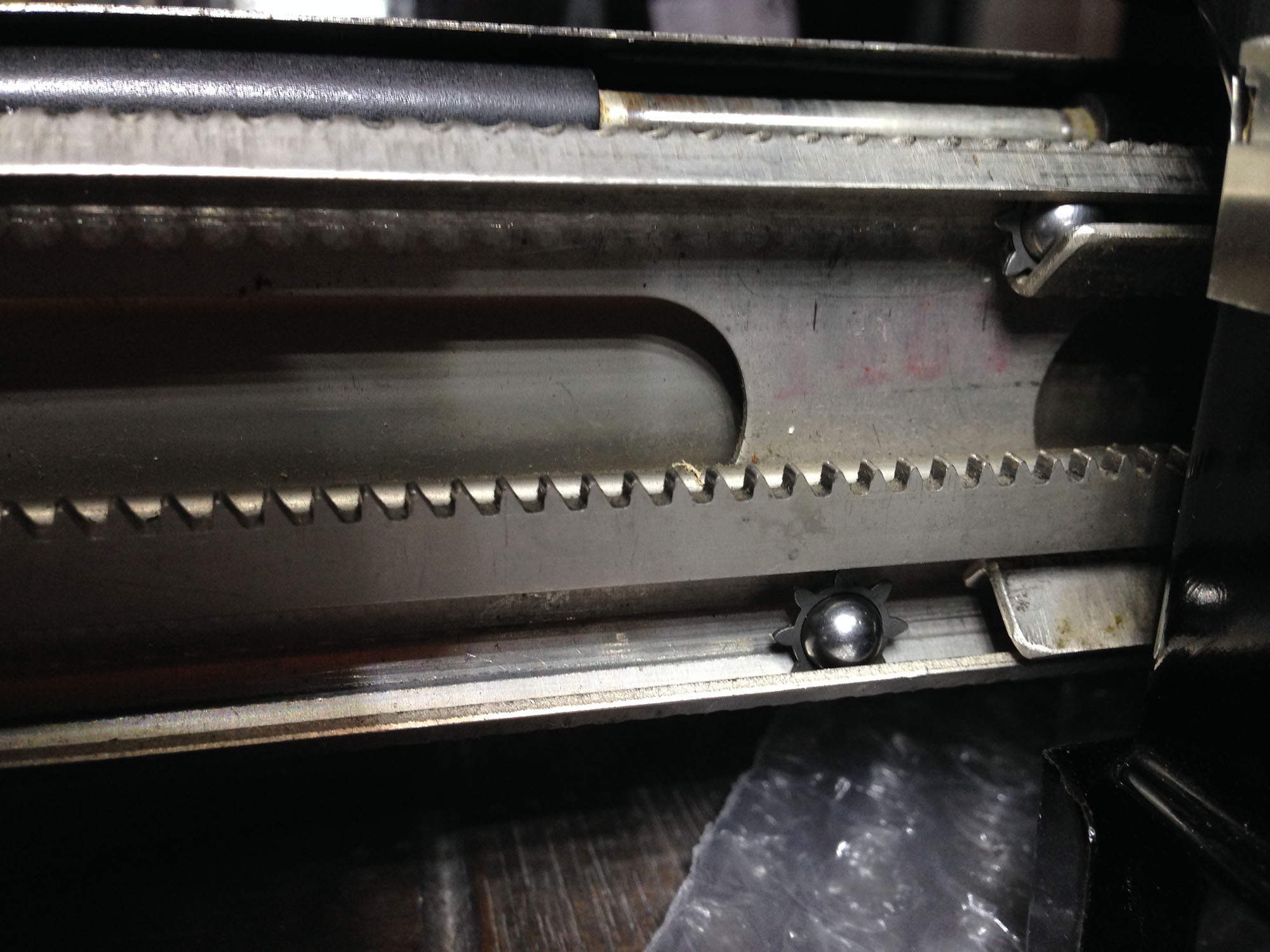
Inserting a bearing ball into the rail
Converting the typewriter into a USB keyboard
For the USB conversion I used a very nice kit made by Jack Zylkin[a]. He sells conversion kits on his website for nearly every model of old typewriter. The kit installation is very easy and Jack provides detailed video tutorials for each machine model on the website.
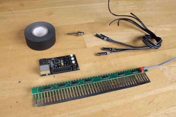
The USB conversion kit
The USB Typewriter Conversion Kit consists of three components:
- The Sensor Strip – a row of 44 gold-plated contacts, attached to a long circuit board which will be mounted underneath the keys, spanning the width of the typewriter. Each time a key is pressed, it touches one of these gold-plated contacts, and this contact is detected by the circuitry.
- The Magnetic Sensors – Since the Space Bar, Shift Key, and Backspace Key do not touch the sensor strip, they are instead detected magnetically. Magnets are attached to these keys, and magnetically-activated switches are glued nearby. These switches can detect the change in the magnetic field whenever these keys are pressed.
- The Control Panel – This circuit board (based on an ATMega32 microcontroller) reads information from the magnetic sensors and the sensor strip, then determines which key has been pressed, sending that information to the computer over USB. The control panel also has several important buttons mounted directly on it: they are CTRL, ALT, and CMD. The Control Panel is mounted to the side of the typewriter, so that these buttons can be accessed easily.
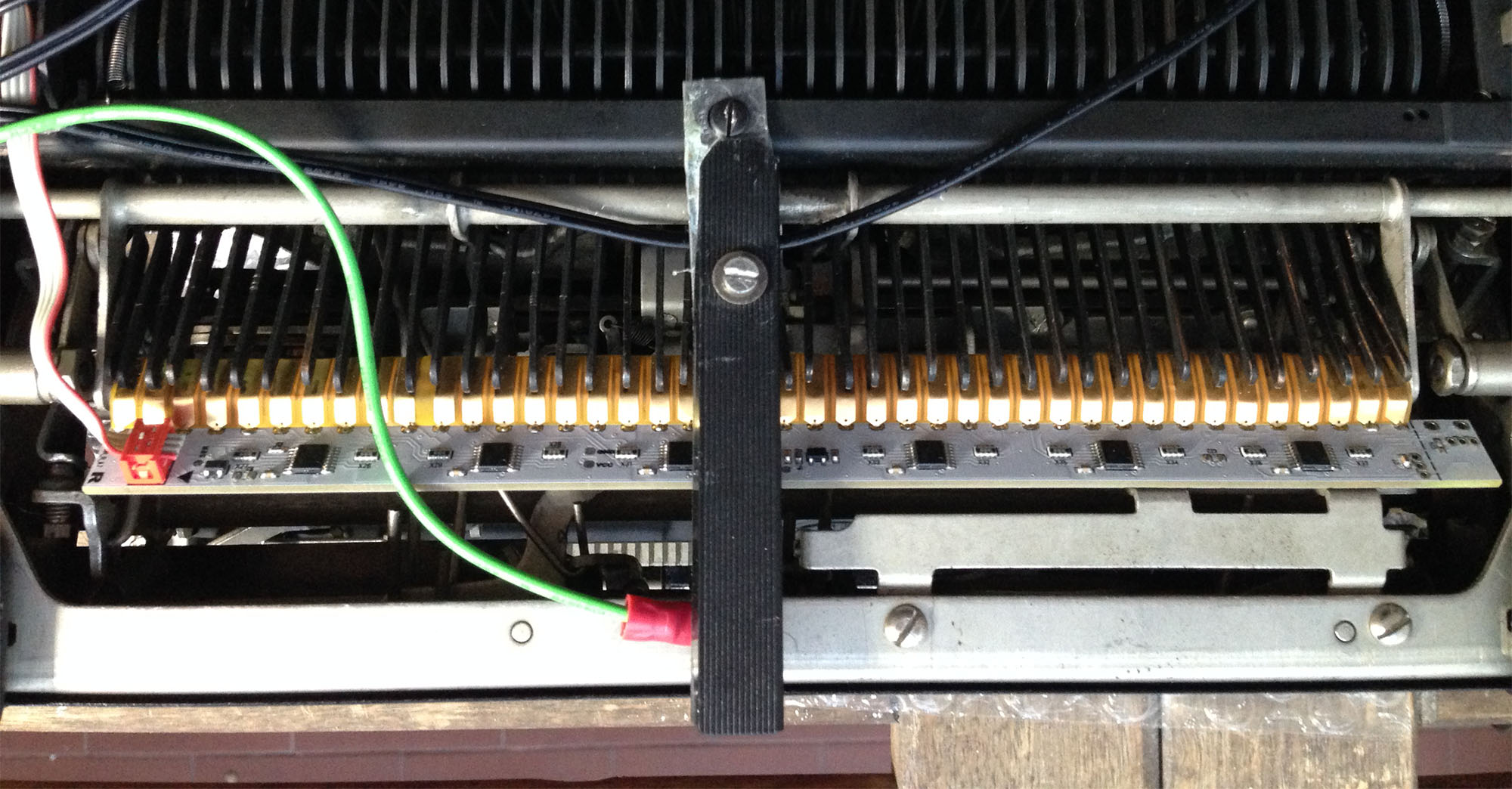
I glued the sensor strip on a steel bar placed on the back of the machine. This bar is raised by the key levers every time you press a key. It activates two mechanisms: the ink ribbon lifting mechanism and the rotation of the ribbon spools. I scratched the surface of each lever’s end to remove the paint allowing for conductivity. The current flows from the machine frame, which is connected to the ground with a green wire, to the gold contact of the key currently pressed via the key lever. A sensitivity adjuster made of a screw attached to a metal plate is used to slightly raise the steel bar in order to avoid any electrical contact with the levers when nothing is pressed.
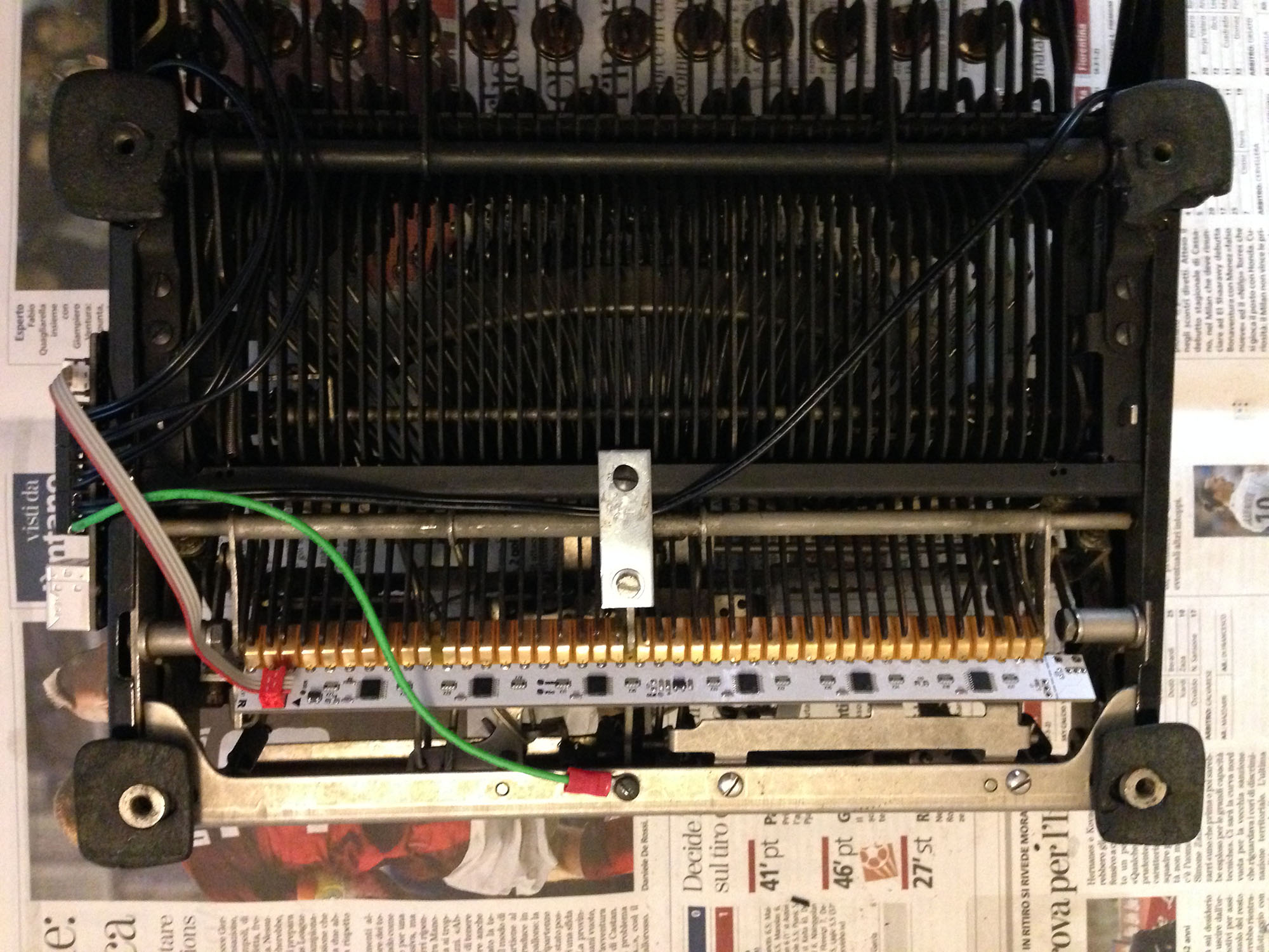
Sensitivity adjuster on top, sensor strip in the middle, green ground on bottom

A magnet for the shift button sensor
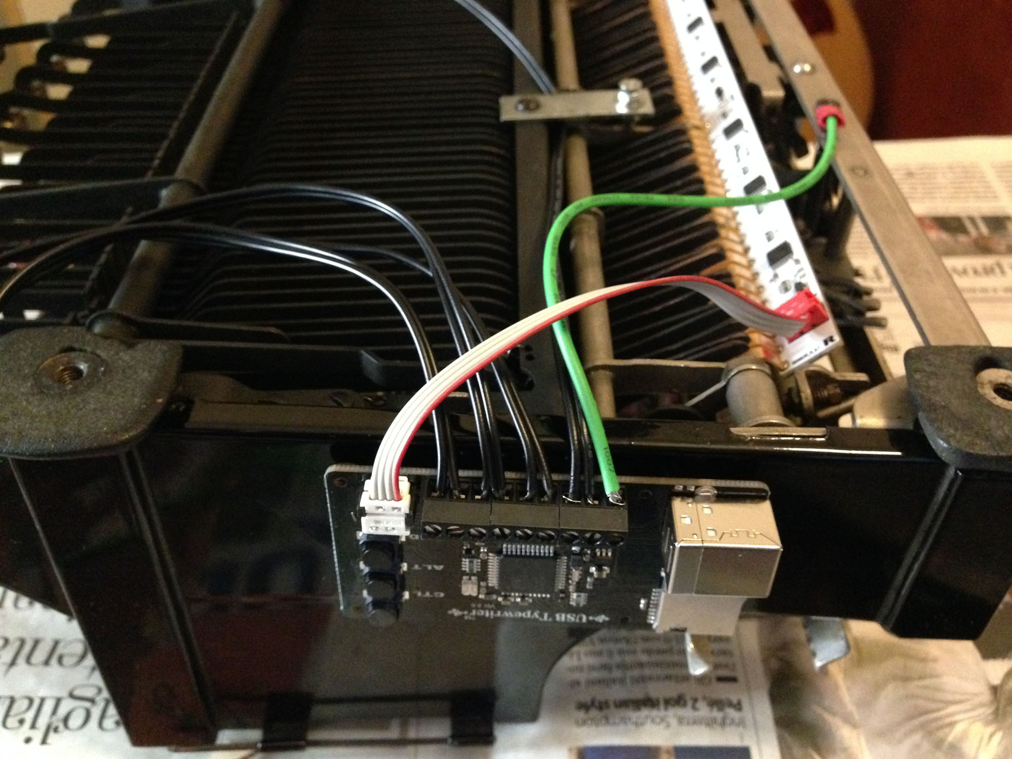
The control panel circuit board (based on an ATMega32 microcontroller) on the side of the machine
While essential for the proper functioning of the USB keyboard, the sensitivity adjuster was causing a problem with the ribbon spools rotation mechanism. This mechanism is very sensitive and stops working when the bar is raised by a few tenths of a millimeter. Being one of the key concepts of this project the preservation of the machine’s standard functioning, I installed a lever on the sensitivity adjuster to easily allow the unlock of back steel bar when the machine is used as a standard typewriter. To put the adjuster in place, just move the lever to its central position while holding down a key to lift up the steel bar and allow the adjuster’screw to shift back to its operational position.
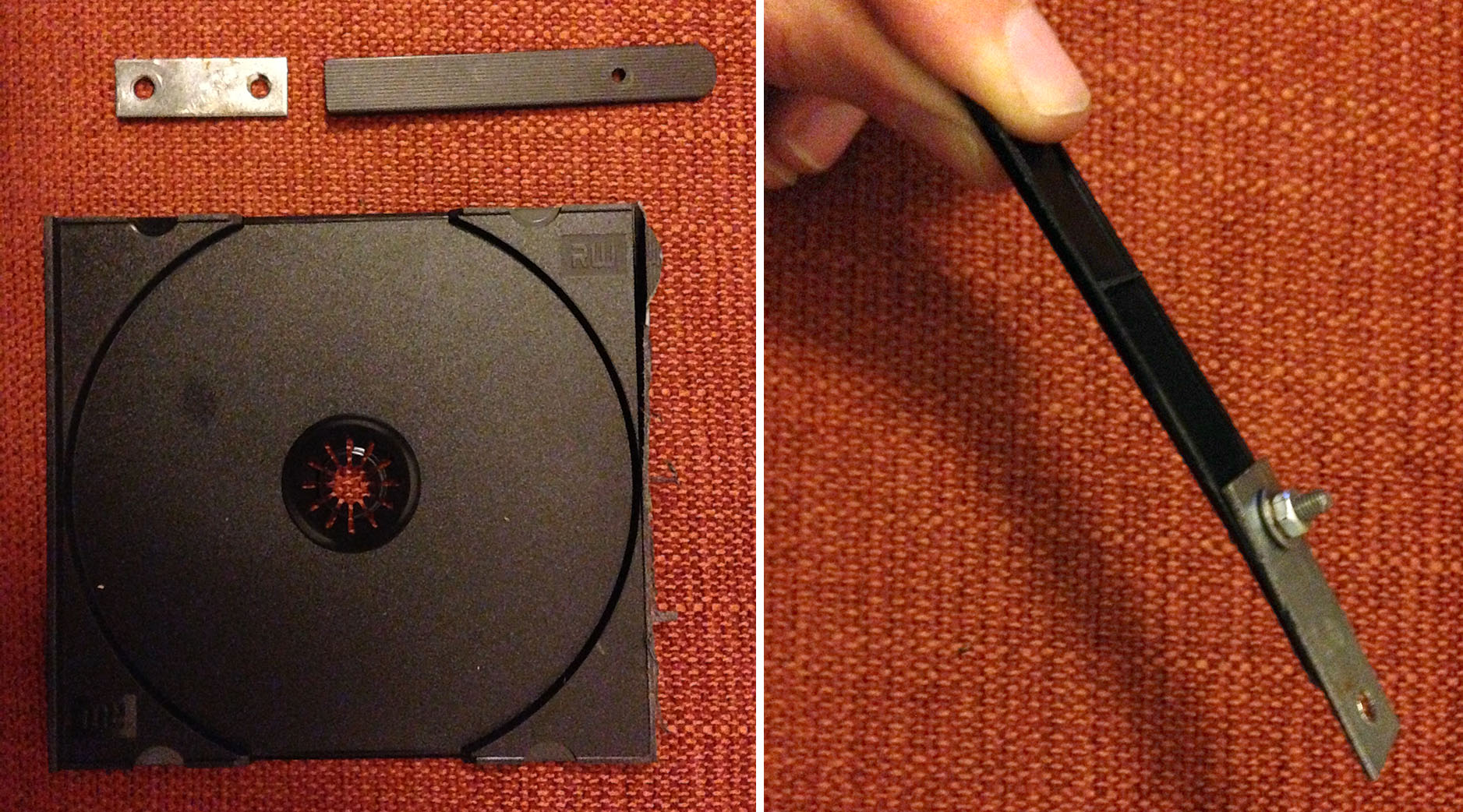
This lever allows for the removal of the sensitivity adjuster when operating in typewriter mode
The sensitivity adjuster lever installed
Building a new wooden base plate
For the installation of the battery and an USB hub, I decided to build a new wooden base plate for the machine. On this plate I created two cavities to host the battery and the hub.
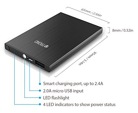 For the battery I used a very thin power bank with 4000 mah capacity and a thickness of 8 millimeters. A hole of 4 mm in my 6 mm tick plywood board allowed enough room for the battery installation. In the same way I installed the USB hub. I also carved an accommodation for the USB cable which was too thick for the space between the board and the bottom of the typewriter.
First I removed all the hardware from the original base plate. Since the hardware was attached to the plate with rivets, I had to remove them using a power drill. I flattened the head of each rivet with a file, in order to gain better grip for the drill.
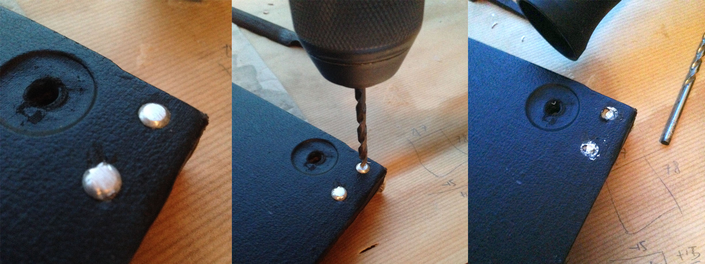
Removing the rivets with a power drill
Then I laser cut a new plate from a piece of poplar plywood with 6 mm thickness and I used some chisels to carve the holes for the battery and the USB hub. The cross grain layers of the plywood make it difficult to carve. I try to work on a layer at a time, going with the grain with my chisel. I also prepare a knife wall all along the perimeter of the hole, to allow for a clean cut along the boundaries. After drilling all the holes for the hardware installation, I covered the plate with a black leather-textured vinyl sheet, very similar to the original coat. Finally I reinstalled all the hardware with bolt and screws and attached the battery and the USB hub.
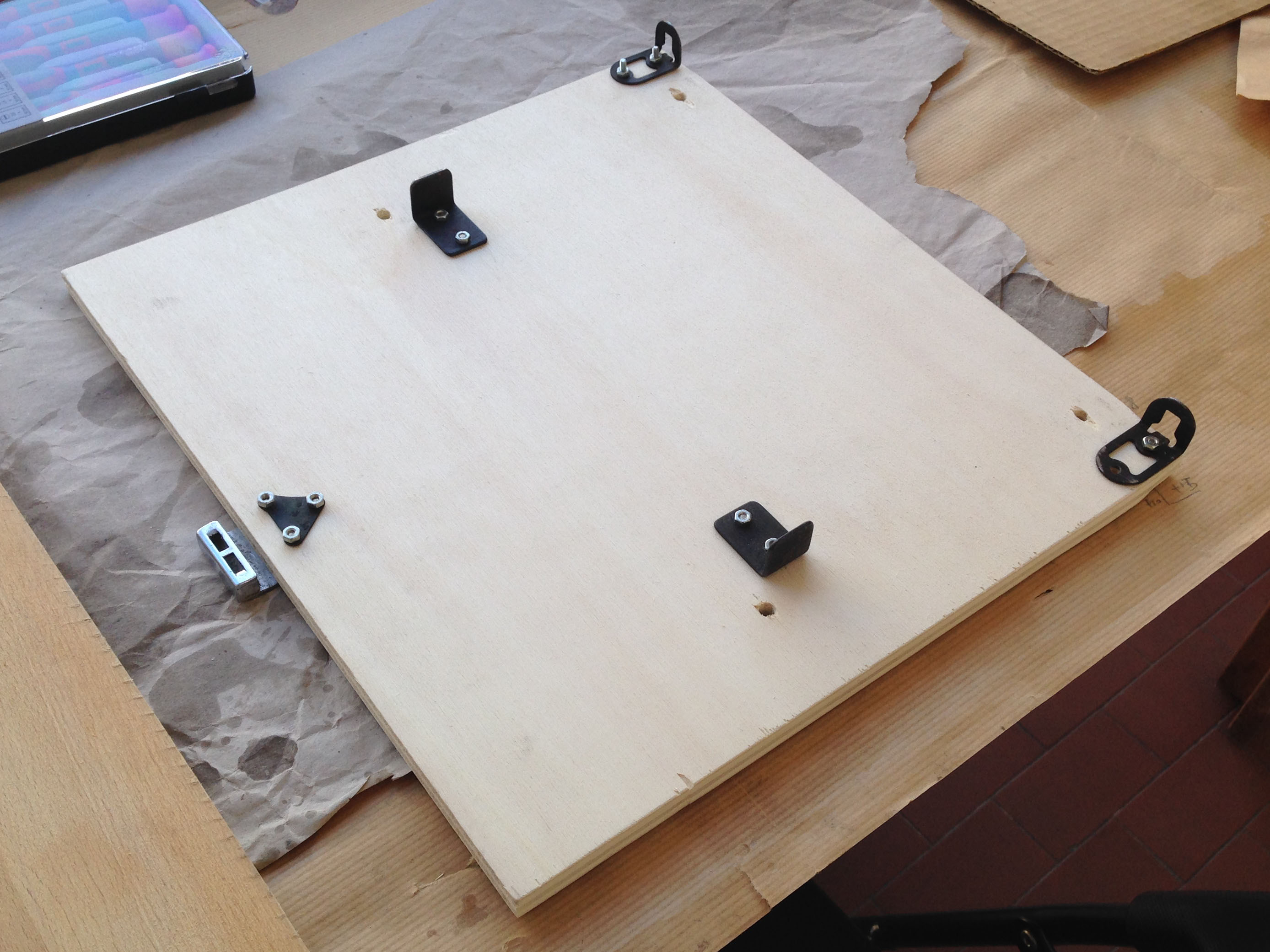
Installing the hardware elements on the wooden plate
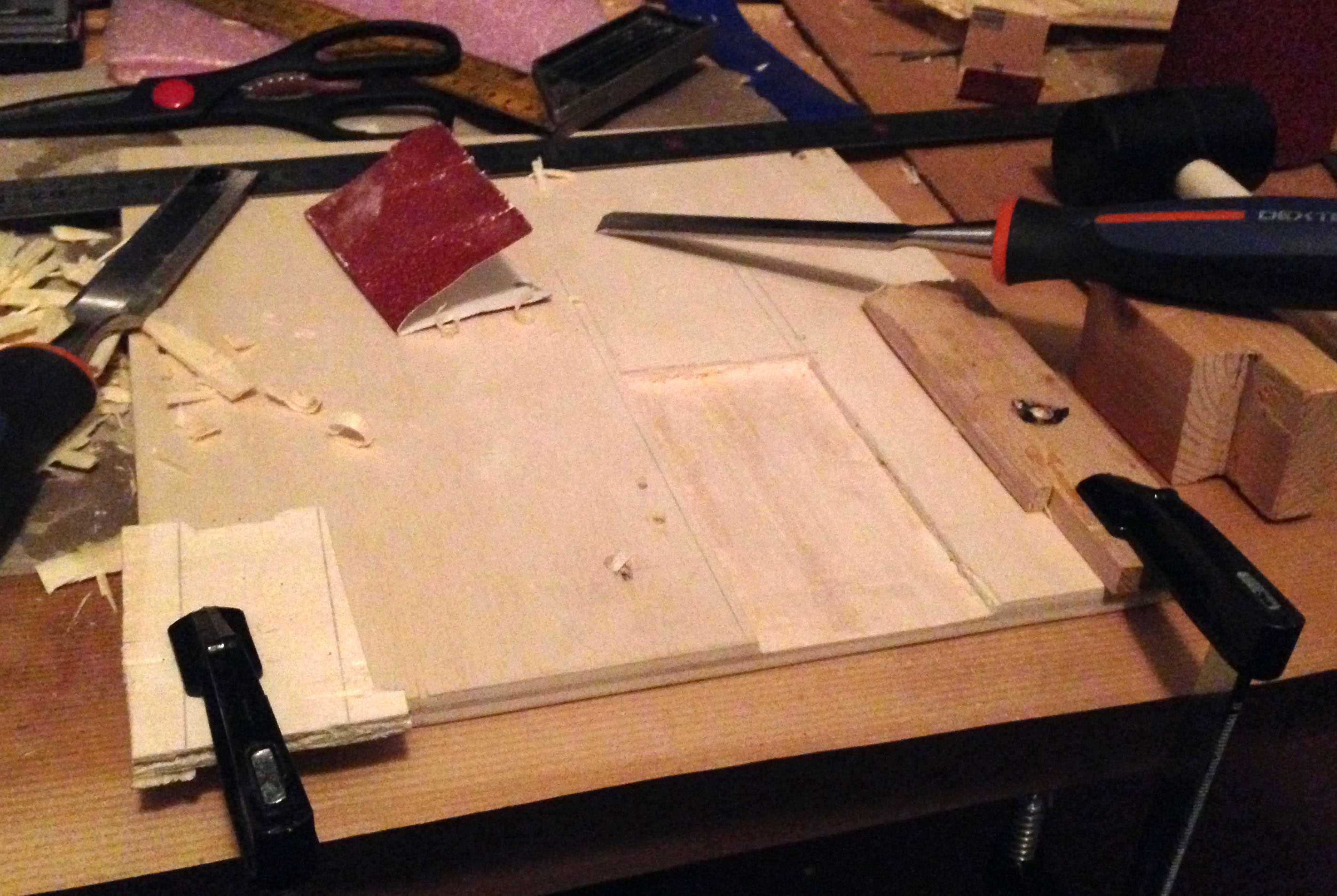
Carving the hole for the battery
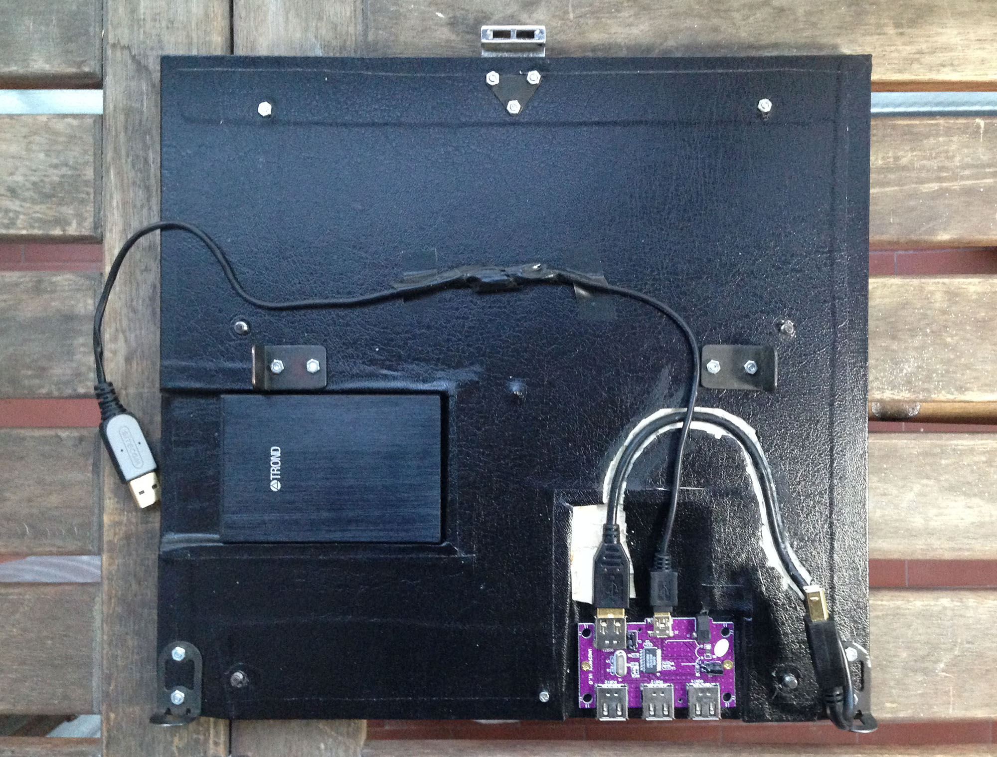
The complete base plate
Setup and protecting the platen
During the electronic operational mode, I’m blocking the carriage in central position by inserting a nail on the rightmost hole of the carriage rail.
The carriage blocking nail
Bundled with the kit comes a rubber strip to install on the type guides near the ink ribbon. It should be used to stop the hammers just before smashing on the typewriter’s platen. This to avoid consuming ink and ruining the rubber surface of the platen, since the hammers are hitting always the same spot during the electronic mode, being the carriage blocked.
Being one of the key concepts of this project the preservation of the original sound and feel of the keyboard, I came up with a different solution to protect the platen during the electronic operational mode; I’m inserting a thin strip of black plastic on the platen as a shield for the impact of the hammers.
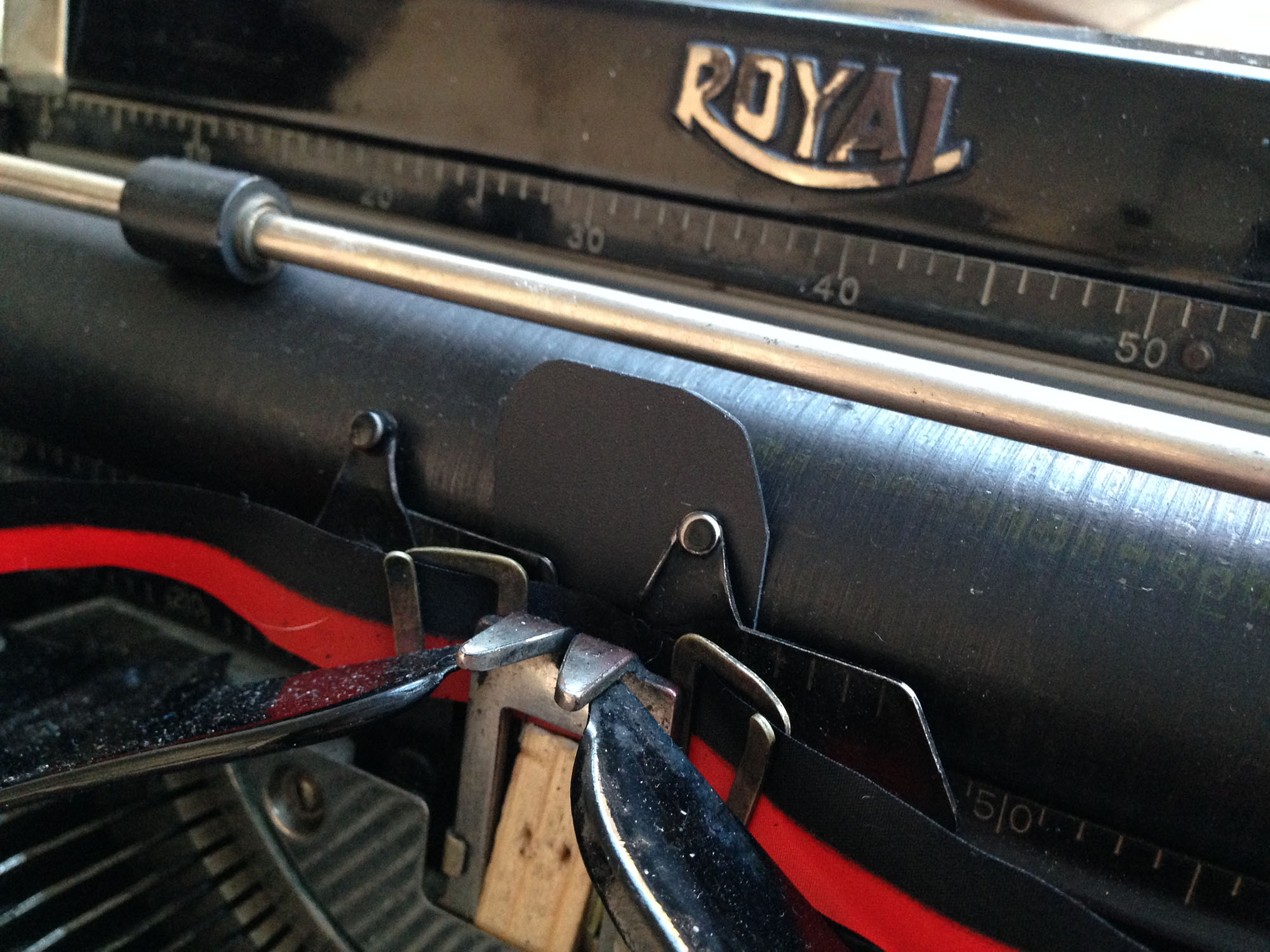
A shield strip protecting the roller

Spacer block, wooden prototype
To avoid ink consumption, I’m setting the color lever into the stencil position. In this position the ribbon is inoperative and won’t be raised at the hammer level when you press a key. Even in this position, I noticed that the ribbon is still lifted a little bit. To block it completely, I made a spacer block to insert into the ribbon holder. I first created a wooden prototype, then I replaced it with a 3D printed version.

Spacer block, 3D printed version
Installing the Raspberry Pi
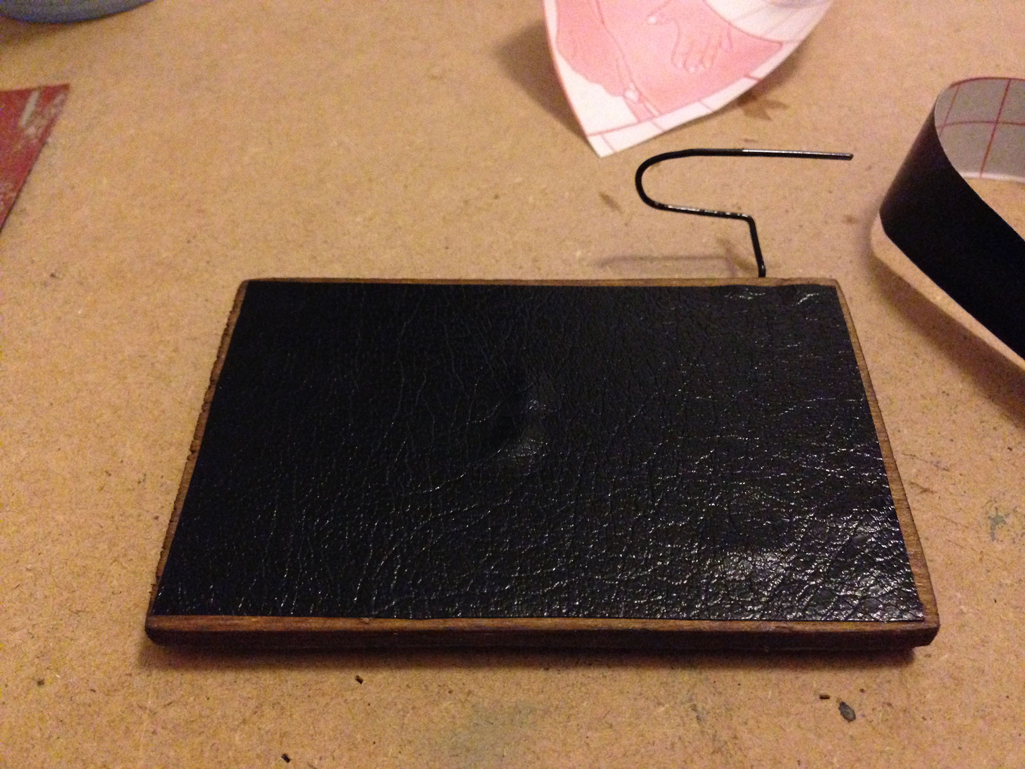
For the computing core of this typewriter laptop I’m using a Raspberry Pi model 3. For its installation I used a wooden board, attached to the right side of the typewriter with a couple of velcro discs. I created a guide for the power cable coming from the battery using some wire.

The Raspberry Pi does not provide any power management mechanism, there isn’t a power switch and when you power off it from software, the system is halting all services but the CPU is still powered. I added a push button to the power cable to easily turn on the system and power it off after a software shutdown.
The RPi is connected to the keyboard via a USB cable running below the machine up to the USB hub, where the keyboard controller is connected.
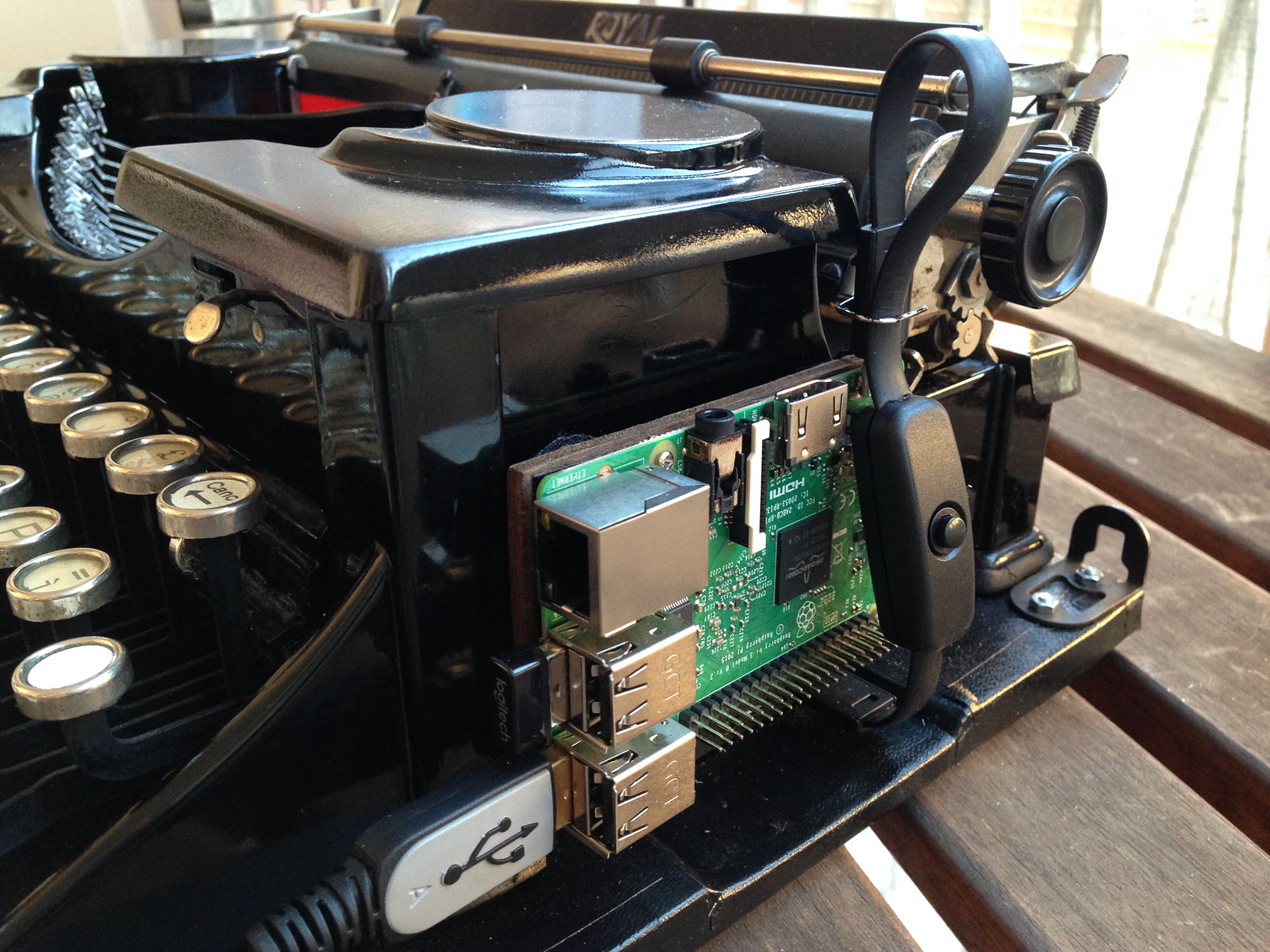
The Raspberry Pi installed on the side. Note the button switch on the power cable.
The display
For the display of this laptop I used a tablet. I like the idea of putting a thin screen over the platen, replacing the paper in a standard typewriter. Here I’m leveraging the fact that the Raspbian, a Linux distro for the RPi, comes with a pre-installed VNC server. This service is advertised to the LAN via the Bonjour protocol. This allows to easy discover and connect a device to the RPi without any manual configuration. You can use any tablet as a display, just install a VNC client and you are ready to stream the RPi desktop.
VNC is a protocol to remote control a machine. Unlike other protocols like Windows Remote Dektop Protocol, you can still control your machine with a mouse and a keyboard while streaming the desktop to a VNC client. This makes VNC perfect for what I’m doing on this project: attach a keyboard and a wireless mouse to the RPi, and using a tablet with a VNC client as a display.
I’m forcing the display resolution of the RPi to 1024×768 to match that of an iPad 2, which I’m using as a display. The resolution is configured in the file /boot/config.txt
|
1 2 3 |
hdmi_force_hotplug=1 hdmi_group=2 hdmi_mode=16 |
The instruction manuals
When I bought the Royal Portable, the instruction manual was not included. Fortunately I found a scan of the original one on this website.
The peculiarity of this manual is the half height of the internal pages, allowing diagrammatic charts of the machine to be always visible on top of the document while reading the instructions.


I have also written a new manual, with the same style of the original and the half height pages, for the electronic version of the typewriter.
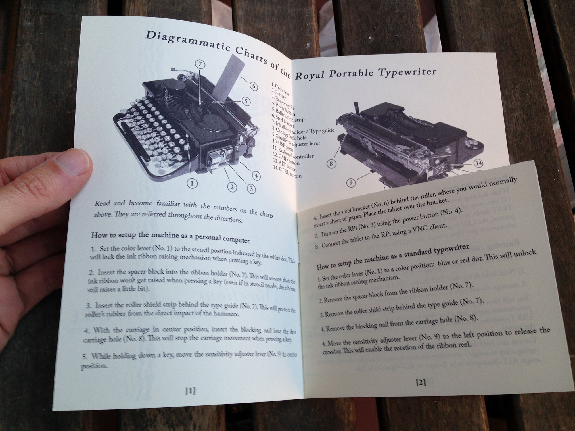
The new manual
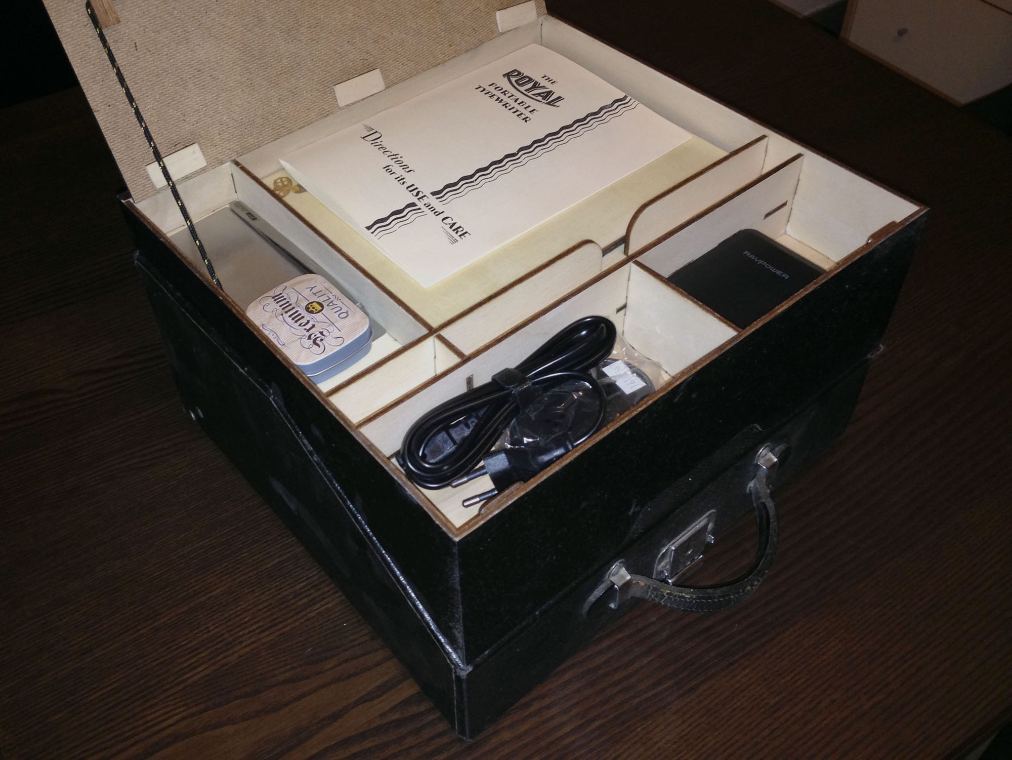
Case extension and accessories
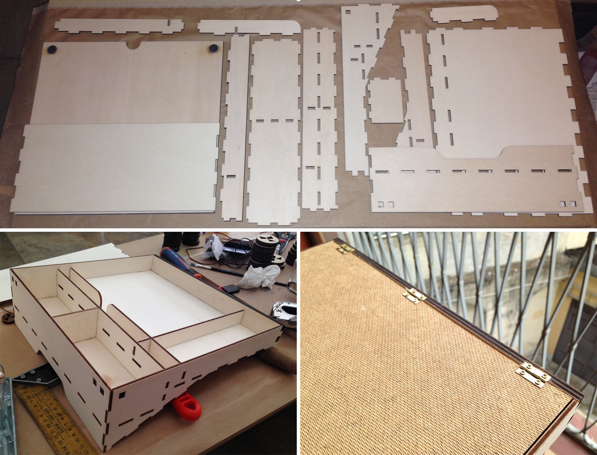
To be fully portable, the typewriter needs a case to store all the accessories and the display. I’ve created a case extension, attached to the original case with velcro discs. I designed the extra case to adapt to the shape of the standard case in order to perfectly sit on its top and resulting in a box-shaped case.
I laser cut the case from 4 mm poplar plywood. I used 6 mm plywood for the back side to make room for the screws of the cover hinges. For the cover I used a sheet of hardwood which is very light and provides some flexibility, avoiding a common problem of thin sheets of plywood which always tend to bend. To lock down the cover I used a couple of neodymium magnets. All the wooden pieces are connected with finger joints. I covered the case with the same leather-textured black vinyl sheet I used for the base plate.
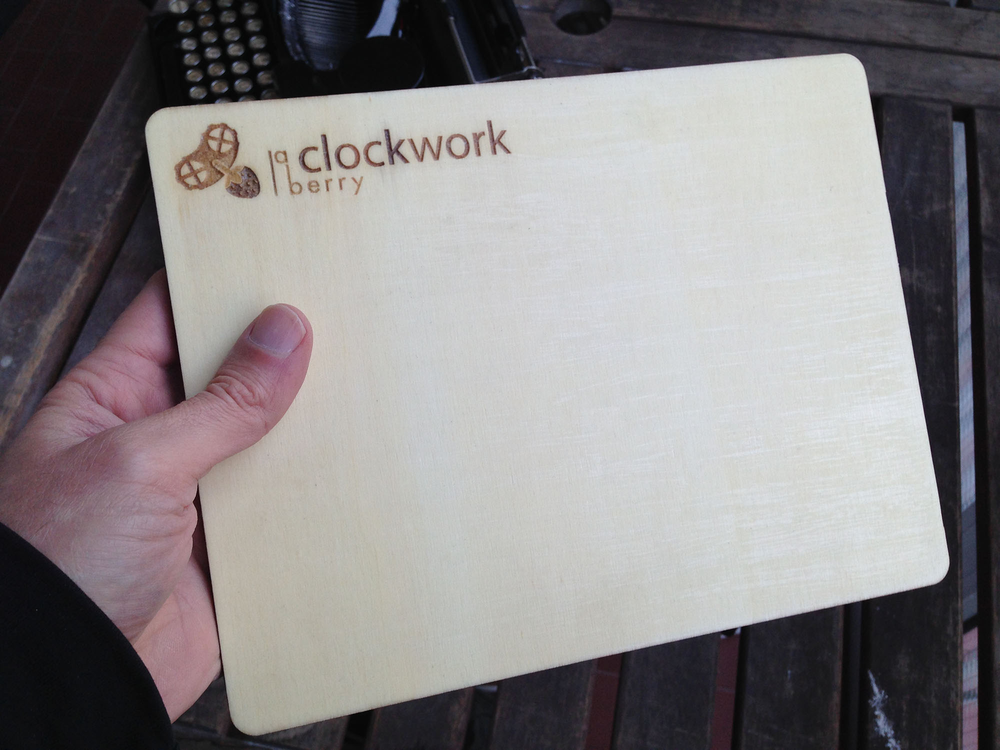 As for the accessories, I’ve created a wooden mouse pad with felt on the bottom side and a laser engrave of my logo on the top. I made it the same size of the ipad to store both in the same slot of the case.
Another thing I’m storing in the case is a USB charging hub to recharge both the ipad and the battery while powering the RPi (the battery I’m using cannot power a device while being recharged) . There are also some tweezers, backup ribbon spools, and a metal box containing the plastic platen shields and the spacer block.
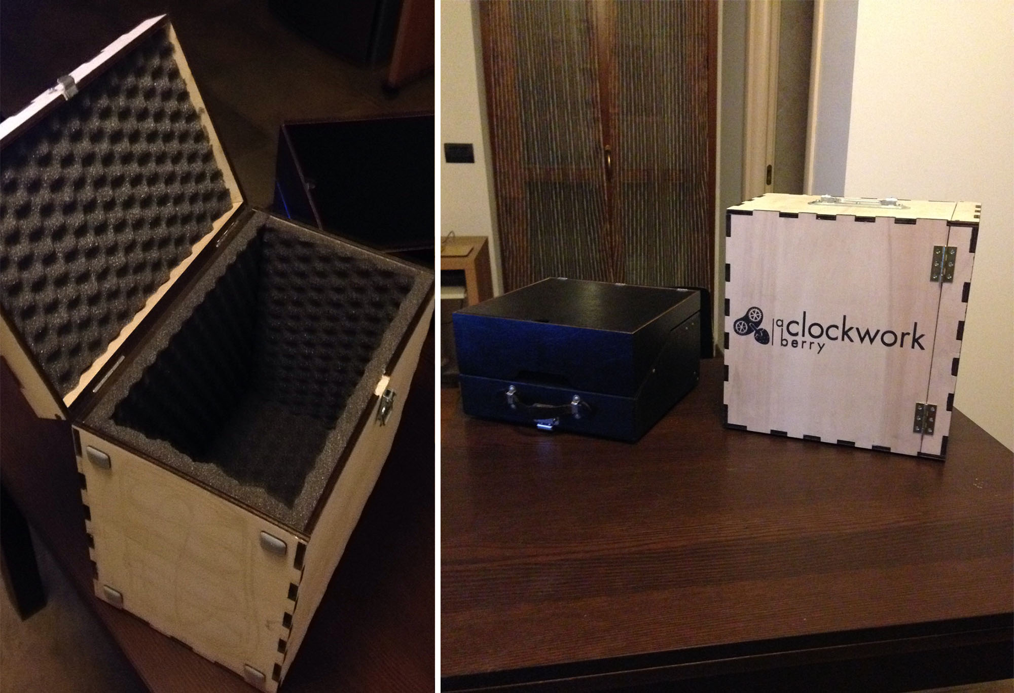
To safely travel with this machine, I’ve built a box with 8 mm poplar plywood and foam covered walls where the typewriter can be safely stored inside it’s case. On the outside of the box I spray painted my logo using a stencil made with a vinyl cutter.
Press
- Una Macchina da scrivere del 1930 trasformata in un computer portatile Steampunk del 2020! – Filoconnesso.it
- Una macchina da scrivere si trasforma in pc. «Vi spiego come fare, in open source» – Corriere della Sera
- Una vecchia macchina per scrivere diventa un pc – Ansa, Roma
- Steampunk Typewriter Laptop, così la macchina da scrivere diventa un pc – Il Messaggero
- Maker Faire Rome: alla scoperta dell’utile e dello stravagante – Tech Princess
- Steampunk Typewriter Laptop – Maker Faire 2017, Rome
Ha! Amazing! This is a wonderful invention. 😀
where can one buy something like this?
Here: https://www.usbtypewriter.com/collections/typewriters